Printer Calibration
While more and more printers nowadays are becoming hands-free and can auto-calibrate themselves, there are some in the market that still need some manual calibration. In addition, knowing how to calibrate a printer will help when an auto-calibration process breaks or if you don't like the values/changes that an auto routine provides.
Rather than reinvent the wheel on this site, I will place links here to excellent guides that already exist.
Curated List of Calibration Sites
- Ellis' Print Tuning Guide — The most comprehensive FDM calibration and tuning reference available. Originally written for Klipper, but the concepts apply broadly to any FDM printer. Covers pressure advance, flow rate, first layer, input shaping, retraction, and much more. This should be your first stop when going deep on print quality.
- Teaching Tech's Calibration Site
- Even if you don't need to calibrate anything right now, I highly suggest at least getting familiar with the site and more importantly, the steps in each of the tabs.
- When using his guide, the tabs follow the order as if you have a new printer. One doesn't have to strictly follow the order, however. In addition, each step has section detailing when that particular calibration should be run. Examples include when a nozzle is changed, adding a new sock, changing out the extruder, and many more.
- Own a Prusa? Please follow their excellent Basic Calibration Guide
- Bambu Lab printer owners: Bambu printers largely auto-calibrate out of the box, so most users will not need to perform manual calibration routinely. However, you can still run manual calibration passes either through the printer's own calibration menu or via OrcaSlicer. See the Bambu Studio/OrcaSlicer Built-in Calibration section below for details on the available calibration tools.
- If you're running Klipper, it is MANDATORY to get very familiar
with their documentation.
- You've been warned. Prepare for lots of frustration and headaches if you are new to Klipper and try to wing it.
- When you're ready to start building your own macros, there is an excellent tutorial here that steps the user from the basics all the way to more advanced uses.
Bambu Studio/OrcaSlicer Built-in Calibration
- Flow rate
- Pressure Advance
- Line method
- Pattern method
- Tower method
- Temp tower
- Retraction test
- Orca Tolerance Test
- Advanced calibration
- Max Volumetric speed
NOTE: After completing the calibration process, remember to create a new project in order to exit the calibration mode.
Flow rate
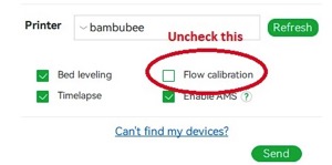
Bambu Lab X1/X1C users
On older firmware, do not select the 'Flow calibration' option. Newer Bambu firmware versions handle this automatically — check the current Bambu documentation to confirm the correct behavior for your firmware version.
 Calibrating the flow rate involves a two-step process.
Steps
- Select the printer, filament, and process you would like to use for the test.
- Select
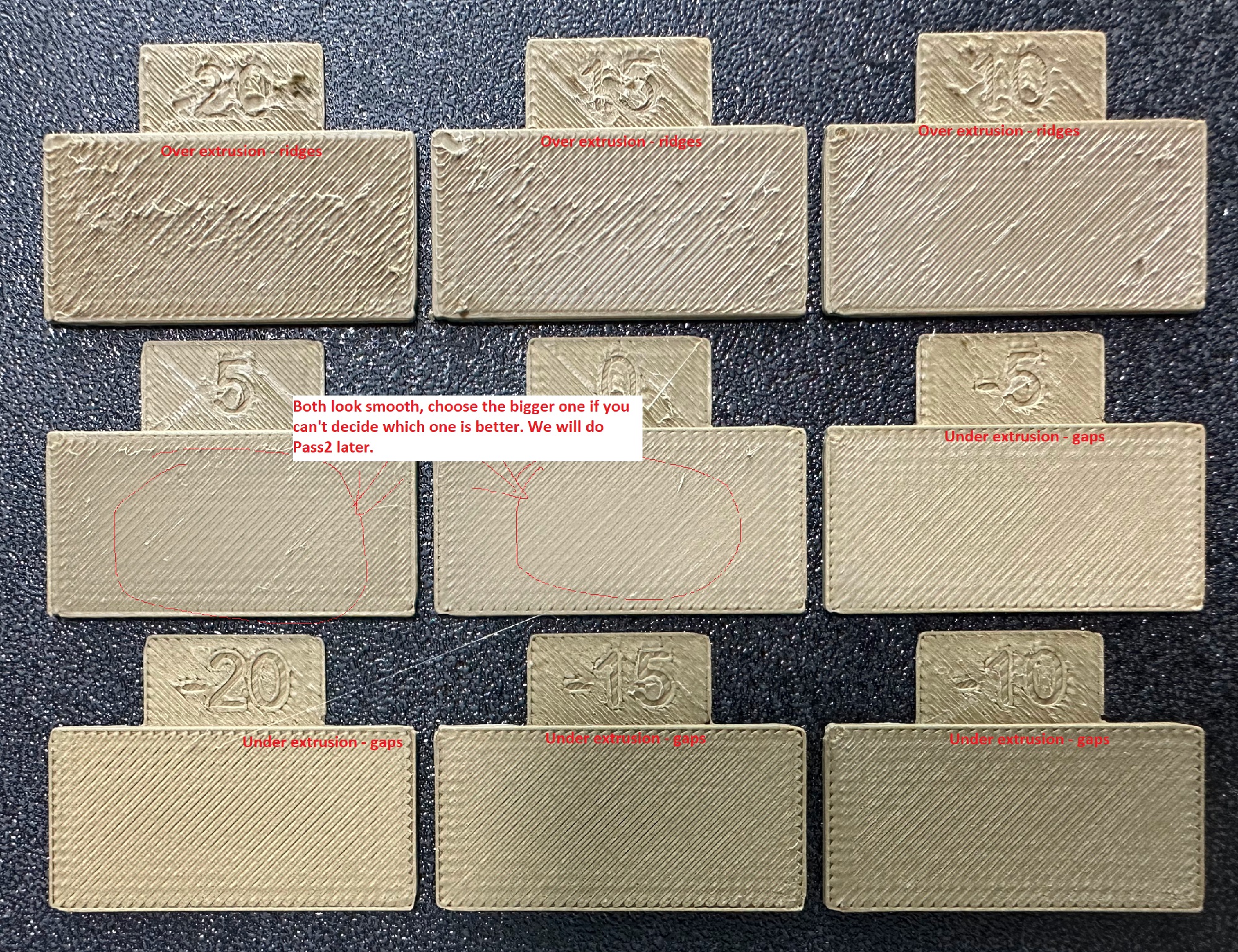
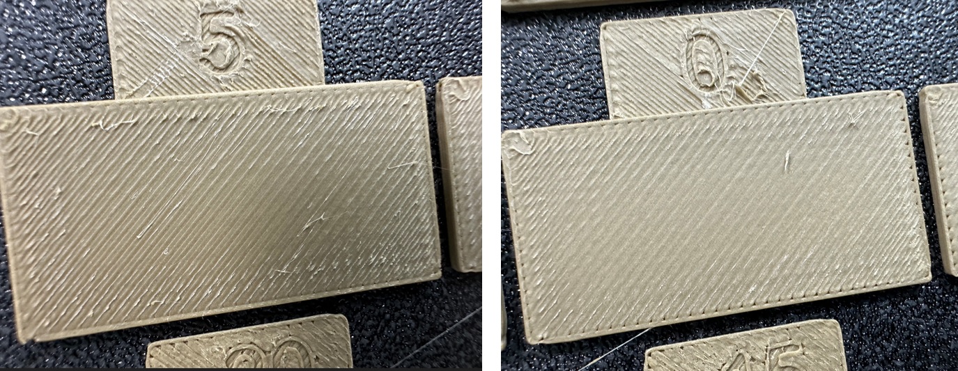
Pass 1in theCalibrationmenu - A new project consisting of nine blocks will be created, each with a different flow rate modifier. Slice and print the project.
-
Examine the blocks and determine which one has the smoothest top surface.
-
Update the flow ratio in the filament settings using the following equation:
FlowRatio_old*(100 + modifier)/100. If your previous flow ratio was0.98and you selected the block with a flow rate modifier of+5, the new value should be calculated as follows:0.98x(100+5)/100 = 1.029. Remember to save the filament profile. - Perform the
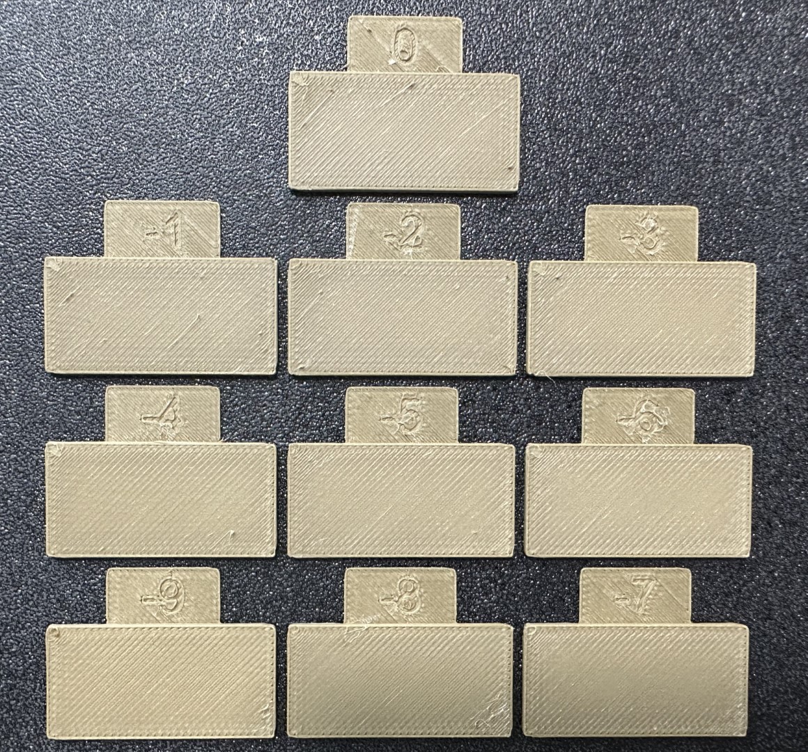
Pass 2calibration. This process is similar toPass 1, but a new project with ten blocks will be generated. The flow rate modifiers for this project will range from-9 to 0. - Repeat steps 4 and 5. In this case, if your previous flow ratio was 1.029 and you selected the block with a flow rate modifier of -6, the new value should be calculated as follows:
1.029x(100-6)/100 = 0.96726. Remember to save the filament profile.

Pressure Advance
Orca Slicer includes three approaches for calibrating the pressure advance value. Each method has its own advantages and disadvantages. It is important to note that each method has two versions: one for a direct drive extruder and one for a Bowden extruder. Make sure to select the appropriate version for your test.
Bambu Lab X1/X1C users
On older firmware, do not select the 'Flow calibration' option when printing. Newer Bambu firmware versions handle this automatically — check the current Bambu documentation to confirm the correct behavior for your firmware version.
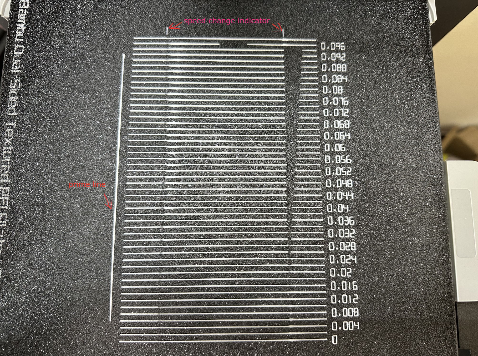
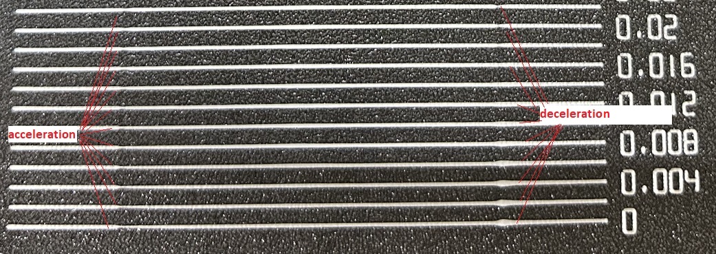
Line method
The line method is quick and straightforward to test. However, its accuracy highly depends on your first layer quality. It is suggested to turn on the bed mesh leveling for this test.
Steps:
- Select the printer, filament, and process you would like to use for the test.
- Print the project and check the result. You can select the value of the most even line and update your PA value in the filament settings.
- In this test, a PA value of
0.016appears to be optimal.

Pattern method
The pattern method is adapted from Andrew Ellis' pattern method generator, which was itself derived from the Marlin pattern method developed by Sineos.
Instructions for using and reading the pattern method are provided in Ellis' Print Tuning Guide, with only a few Orca Slicer differences to note.
First and foremost, when you initiate the test, you'll only see a small rectangular prism on the plate. This object serves a few purposes:
- The test pattern itself is added in as custom G-Code at each layer, same as you could do by hand actually. The rectangular prism gives us the layers in which to insert that G-Code. This also means that you'll see the full test pattern when you move to the Preview pane
- The prism acts as a handle, enabling you to move the test pattern wherever you'd like on the plate by moving the prism
- The filament selected for the prism is also used for the test pattern
Next, Ellis' generator provided the ability to adjust specific printer, filament, and print profile settings. You can make these same changes in Orca Slicer by adjusting the settings in the Prepare pane as you would with any other print. When you initiate the calibration test, Ellis' default settings are applied. A few things to note about these settings:
- Ellis specified line widths as a percent of filament diameter. The Orca pattern method does the same to provide its suggested defaults, making use of Ellis' percentages in combination with your specified nozzle diameter
- In terms of line width, the pattern only makes use of the
DefaultandFirst layerwidths - In terms of speed, the pattern only uses the
First layer speed -> First layerandOther layers speed -> Outer wallspeeds - The infill pattern beneath the numbers cannot be changed because it's not actually an infill pattern pulled from the settings. All of the pattern G-Code is custom written, so that "infill" is, effectively, hand-drawn and so not processed through the usual channels that would enable Orca to recognize it as infill
Tower method
The tower method may take a bit more time to complete, but it does not rely on the quality of the first layer.
The PA value for this test will be increased by 0.002 for every 1 mm increase in height. (NOTE 0.02 for Bowden)
Steps:
- Select the printer, filament, and process you would like to use for the test.
- Examine each corner of the print and mark the height that yields the best overall result.
- I selected a height of 8 mm for this case, so the pressure advance value should be calculated as
0.002x8 = 0.016.
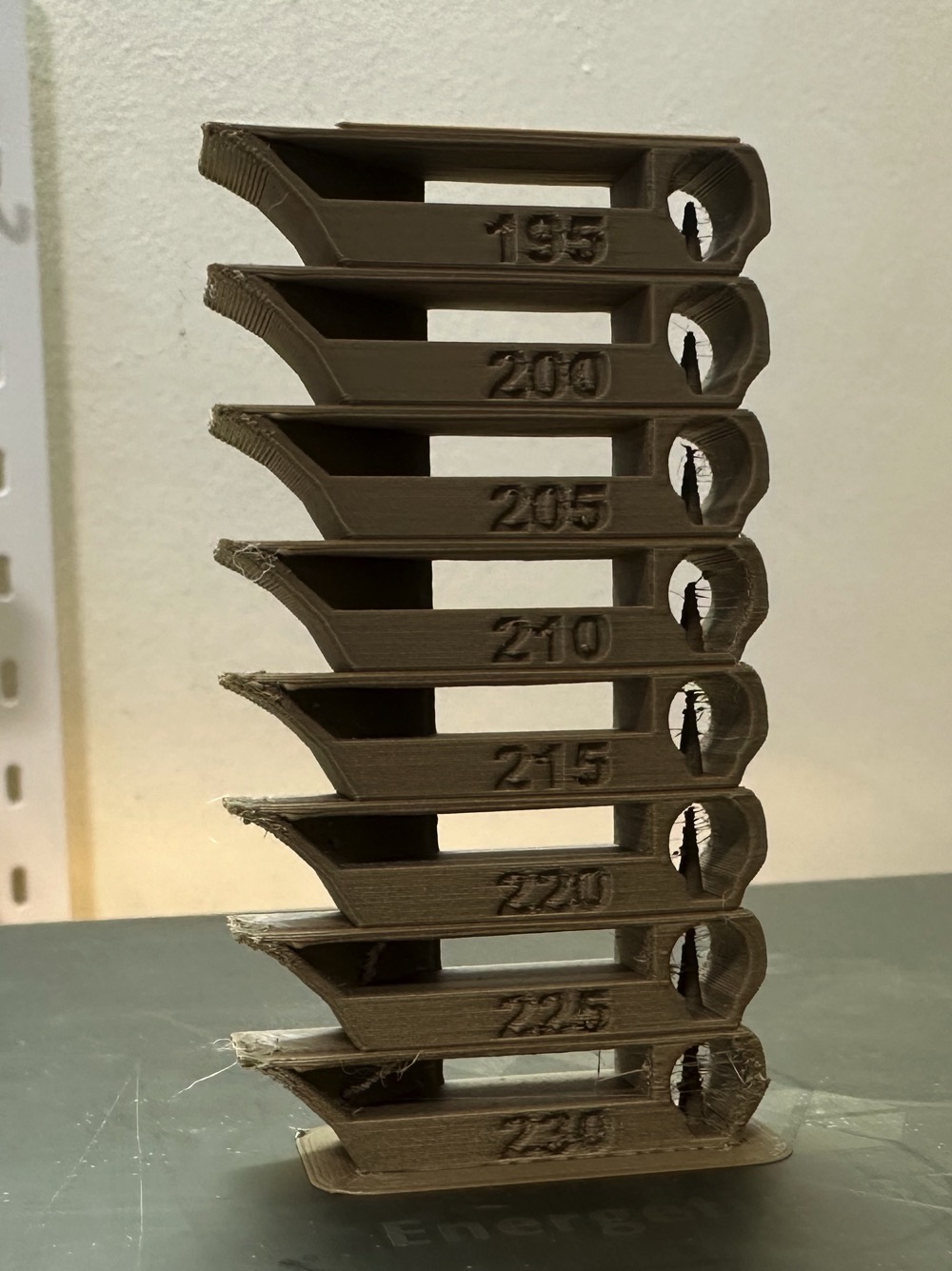
Temp Tower
Temp tower is a straightforward test. The temp tower is a vertical tower with multiple blocks, each printed at a different temperature. Once the print is complete, we can examine each block of the tower and determine the optimal temperature for the filament. The optimal temperature is the one that produces the highest quality print with the least amount of issues, such as stringing, layer adhesion, warping (overhang), and bridging.
Retraction test
This test generates a retraction tower automatically. The retraction tower is a vertical structure with multiple notches, each printed at a different retraction length. After the print is complete, we can examine each section of the tower to determine the optimal retraction length for the filament. The optimal retraction length is the shortest one that produces the cleanest tower.
In the dialog, you can select the start and end retraction length, as well as the retraction length increment step. The default values are 0mm for the start retraction length, 2mm for the end retraction length, and 0.1mm for the step. These values are suitable for most direct drive extruders. However, for Bowden extruders, you may want to increase the start and end retraction lengths to 1mm and 6mm, respectively, and set the step to 0.2mm.
Note: When testing filaments such as PLA or ABS that have minimal oozing, the retraction settings can be highly effective. You may find that the retraction tower appears clean right from the start. In such situations, setting the retraction length to 0.2mm - 0.4mm using Orca Slicer should suffice. On the other hand, if there is still a lot of stringing at the top of the tower, it is recommended to dry your filament and ensure that your nozzle is properly installed without any leaks.
Orca Tolerance Test
This tolerance test is specifically designed to assess the dimensional accuracy of your printer and filament. The model comprises a base and a hexagon tester. The base contains six hexagon hole, each with a different tolerance: 0.0mm, 0.05mm, 0.1mm, 0.2mm, 0.3mm, and 0.4mm. The dimensions of the hexagon tester are illustrated in the image.
You can assess the tolerance using either an M6 Allen key or the printed hexagon tester.
Advanced Calibration
Max Volumetric speed
This is a test designed to calibrate the maximum volumetric speed of the specific filament. The generic or 3rd party filament types may not have the correct volumetric flow rate set in the filament. This test will help you to find the maximum volumetric speed of the filament.
You will be prompted to enter the settings for the test: start volumetric speed, end volumetric speed, and step. It is recommended to use the default values (5mm³/s start, 20mm³/s end, with a step of 0.5), unless you already have an idea of the lower or upper limit for your filament. Select "OK", slice the plate, and send it to the printer.
Once printed, take note of where the layers begin to fail and where the quality begins to suffer. Pay attention to changes from matte to shiny as well.
Using calipers or a ruler, measure the height of the print at that point. Use the following calculation to determine the correct max flow value: start + (height-measured * step) . For example in the photo below, and using the default setting values, the print quality began to suffer at 19mm measured, so the calculation would be: 5 + (19 * 0.5) , or 13mm³/s using the default values. Enter your number into the "Max volumetric speed" value in the filament settings.
You can also return to OrcaSlicer in the "Preview" tab, make sure the color scheme "flow" is selected. Scroll down to the layer height that you measured, and click on the toolhead slider. This will indicate the max flow level for your filament.
Tip
You may also choose to conservatively reduce the result by 5–10% to ensure print quality.
Resin Printer Calibration
Resin printers (MSLA/LCD and DLP) require a different calibration mindset than FDM machines. There are no temperatures to tune, no flow rates to dial in, and no motion artifacts to chase down. What you are calibrating instead is light — how much UV energy reaches the resin, for how long, and where it lands on the build plate. Get those three things right and the printer will be highly repeatable.
The steps below apply broadly to consumer MSLA printers such as the Elegoo Mars and Saturn series, Anycubic Photon Mono series, Phrozen Sonic series, and similar machines running Chitubox, Lychee Slicer, or their manufacturer's bundled slicer.
Warning
Resin is a chemical hazard. Always wear nitrile gloves and work in a well-ventilated area or under an activated-carbon fume hood. Do not allow uncured resin to contact skin, and dispose of resin-contaminated IPA and paper towels per your local regulations — do not pour down the drain.
Build Plate Leveling
Proper build plate tramming is the foundation of every successful resin print. If the plate is not parallel to the FEP film at the correct zero-gap distance, first layers will either peel off the plate or crush against the FEP and cause suction failures or screen damage.
Does your printer auto-level? Some machines (notably the Elegoo Saturn 4 Ultra, Anycubic Photon Mono M7 Pro, and a growing number of 2024–2025 releases) include motorized auto-leveling that tramms the plate on first use. If your printer has this feature, run it per the manufacturer's procedure and skip the manual steps below. Check that the auto-level result feels correct by doing the paper test afterward.
Manual leveling — the paper/card method:
- Home the printer via the touchscreen (
Tools > Move > Home). - Disable the stepper motors (or use the
Releaseoption) so the build plate can be moved by hand. - Place a single sheet of standard copy paper (≈ 0.1 mm) on the FEP film, centered.
- Loosen the build plate locking bolts — usually 4 screws around the plate clamp — just enough that the plate can pivot freely but will stay where pushed.
- Lower the plate by hand until it rests flat on the paper across its full surface. Apply gentle even pressure so the plate self-tramms against the FEP.
- While holding the plate down, re-tighten the locking bolts in a diagonal/cross pattern (same principle as wheel lug nuts) to avoid introducing tilt.
- Zero the Z-axis on the touchscreen (
Tools > Manual > Z = 0or equivalent). - Raise the plate, remove the paper, and test the zero: lower the plate back to Z=0 and verify it sits uniformly close to the FEP with no rocking.
Tip
A single sheet of standard copy paper gives approximately 0.1 mm of clearance, which works for most standard resins. For resins with aggressive bottom layer exposure (e.g., ABS-like or engineering resins), some users prefer a slightly tighter zero with a business card (~0.2 mm). Experiment if you see consistent first-layer failures despite correct exposure.
Note
After leveling, always run a small test print (a simple disc or the first 3–4 layers of any model) before committing to a long print. This confirms the zero is correct without wasting resin.
4-screw tram verification: On machines where the 4 locking screws are accessible individually (common on Saturn and similar large-format printers), after the initial paper level, do a second check:
- Move the plate to Z = 0.
- Slide paper under each corner of the plate individually.
- Resistance should be equal at all four corners. If one corner is tighter or looser, re-loosen the lock screws, correct the tilt by hand, and re-tighten.
Exposure Calibration
Exposure time is the single most impactful tunable variable on a resin printer. Too little and layers fail to cure fully, producing soft, brittle prints or total adhesion failures. Too much and fine details bloom, small holes close up, and layer lines become visible as overcure halos.
Every resin + printer combination requires its own exposure values. Do not assume that settings from one machine will transfer to another, even within the same product line — LCD panels degrade over time, and light output varies between units.
Running a RERF (Resin Exposure Range Finder) test
RERF is the fastest way to bracket your normal layer exposure. It prints a small matrix of test tiles, each at a different exposure time, in a single print.
- In Chitubox: Go to
Calibration > RERF. Set your anticipated exposure range (e.g., 2.0 s to 4.5 s in 0.5 s steps for a 405 nm mono LCD). Slice and print. - In Lychee Slicer: Use
Tools > Exposure Finder. Configure the same range. - Examine the printed tiles. Look for:
- Undercured tile: Surface is tacky or waxy; details are soft; the tile may flex excessively.
- Overcured tile: Features are filled in or bloomed; sharp corners are rounded; small text loses legibility.
- Target tile: The first tile where details are crisp, surfaces are fully hard, and small features are still distinct. This is your starting normal layer exposure.
- Set the identified exposure time in your resin profile and run a dimensional accuracy test (see below) to confirm.
Running an AmeraLabs Town calibration print
The AmeraLabs Town is a purpose-built calibration model that tests a wider range of features than a simple tile matrix: thin walls, pillars, arches, embossed and recessed text, bridges, and holes of graduated sizes. It is the most comprehensive single-print exposure calibration available for consumer MSLA printers.
- Download the Town STL from AmeraLabs' site and import it into your slicer.
- Use your RERF-derived exposure time as a starting point.
- Print the model without supports — it is designed to print flat on the build plate.
- Evaluate the result against the AmeraLabs scoring guide:
- Thin pillars and walls should stand without warping.
- The smallest text should be legible.
- Arched bridges should be complete and not sagging.
- Graduated holes should be distinguishable at the correct sizes.
- Adjust exposure up or down in 0.1–0.2 s increments and reprint until the model scores cleanly.
Note
Bottom layer exposure (the first N layers that bond to the build plate) is calibrated separately from normal layer exposure. Bottom layers are typically exposed 8–12× longer than normal layers to ensure plate adhesion. Start with the manufacturer-recommended bottom exposure for your resin, then dial it down if you see elephant foot (flaring at the base of the model).
Tip
UVtools (free, open-source) can analyze a
sliced .ctb, .photon, or .pwmx file and generate an exposure matrix
natively from any model — a powerful alternative to slicer-specific RERF tools,
and one of the best ways to tune multiple exposure variables simultaneously.
Dimensional Accuracy / XY Calibration
Even with correct exposure, MSLA printers can produce parts that are consistently over- or under-sized in the XY plane. This is caused by light bleed (curing slightly beyond the intended pixel boundary), resin shrinkage, or minor inaccuracies in the LCD panel's effective pixel pitch.
Z-axis accuracy is generally excellent on resin printers and rarely needs adjustment — layer height is mechanically defined by the lead screw.
- Print a known-dimension calibration object. A flat disc or square (40–50 mm across) with no supports works well.
- Allow the print to fully post-cure before measuring — uncured or partially cured resin will continue to shrink slightly.
- Measure across two perpendicular axes with calipers.
-
Calculate the correction factor for each axis:
Scale correction = (nominal dimension / measured dimension) × 100%For example: nominal = 50.00 mm, measured = 49.65 mm →
(50.00 / 49.65) × 100 = 100.71% -
Apply the correction in your slicer's printer profile:
- Chitubox:
Printer Settings > Scale Compensation(enter as a percentage offset, e.g.,+0.71%). - Lychee Slicer:
Printer > Scalefields for X and Y separately. - UVtools: Apply as a morph/expand operation on the sliced file.
- Reprint and re-measure. Iterate until the measured dimension is within ±0.1 mm of nominal for a 50 mm reference object.
Note
Measure at room temperature and after a full post-cure cycle. Resin that has been washed in IPA but not yet post-cured will read slightly larger than the final cured dimension.
Tip
If X and Y deviate significantly from each other (more than ~0.3 mm on a 50 mm span), check that the LCD panel is seated squarely and that the build plate is not introducing tilt. Asymmetric shrinkage across axes is more often a hardware alignment issue than a slicer compensation problem.
FEP Film Condition
FEP (or nFEP/ACF on newer machines) is a consumable. A scratched, cloudy, or damaged FEP will scatter UV light before it reaches the resin, requiring higher exposure times and producing lower-detail prints. This is often mistaken for a resin or exposure problem.
Inspect the FEP before every session:
- Cloudiness or milkiness: Replace the film. A fresh FEP is optically clear.
- Scratches: Minor surface scratches from the scraper are normal. Deep gouges or cracks — replace.
- Loose tension: Press the center of the FEP from below. It should feel taut like a drum, not sag or crinkle. A loose FEP causes suction cup failures and layer separation artifacts.
FEP replacement tension (where manually tensioned, not pre-tensioned cartridges): tighten frame screws in a cross pattern, gradually, to achieve even tension. Over-tightening will bow the resin vat frame and introduce optical distortion.
Warning
When replacing FEP or nFEP, do not use steel scrapers or sharp metal tools on the new film surface. Use a soft plastic scraper or the edge of a credit card to remove cured resin remnants.
Z-Offset Fine-Tuning
After build plate leveling, the Z-offset defines the exact gap between the plate and the FEP at the first layer. Most printers set this during the leveling procedure (setting Z=0 with the paper method), but fine-tuning is sometimes needed.
Signs the Z-offset needs adjustment:
- Too close: First layers are very thin and spread laterally (elephant foot), or the print is impossible to remove from the plate without damage.
- Too far: First layers are thick and rounded at the base, or prints fail to adhere and peel off during the print.
Adjust in 0.01–0.05 mm increments via the printer's touchscreen Z-offset setting (available on most modern machines without re-leveling) and reprint a single-layer test until the first layer is the correct nominal thickness.
Anti-Aliasing and Image Blur Settings
Most modern MSLA printers and slicers offer anti-aliasing (AA) and image blur (also called "grey level" smoothing) settings. These soften the hard pixel boundaries of the LCD mask to produce smoother curved surfaces and reduce the visible stairstepping effect on curved geometry.
- Anti-aliasing level: Common options are 2×, 4×, or 8×. Higher values produce smoother edges but can slightly reduce sharp detail on very fine features. 4× is a reasonable default for most models.
- Image blur / grey blur: Applies a Gaussian-style blur to pixel edges, further smoothing transitions. Overuse blurs fine-detail text and thin features.
- Interaction with exposure: AA and blur settings interact with your exposure time. When changing these settings, re-run an AmeraLabs Town or RERF to confirm your exposure time is still optimal — AA can cause slight underexposure at edges if exposure is already at the low end.
Note
These settings are found in the printer or slice settings panel of Chitubox and Lychee, and can also be applied post-slice in UVtools. They are printer-specific — some older machines or firmware versions do not support grey-level AA.
Credits:
- The Flowrate test and retraction test is inspired by SuperSlicer
- The PA Line method is inspired by K-factor Calibration Pattern
- The PA Tower method is inspired by Klipper
- The temp tower model is remixed from Smart compact temperature calibration tower
- The max flowrate test was inspired by Stefan(CNC Kitchen), and the model used in the test is a remix of his Extrusion Test Structure.